|
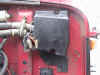
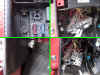
Locate the bulkhead cover on
the driver's side of the firewall. Remove the two 11 mm bolts which hold
the cover in place. Remove the cover and set aside.
|
|
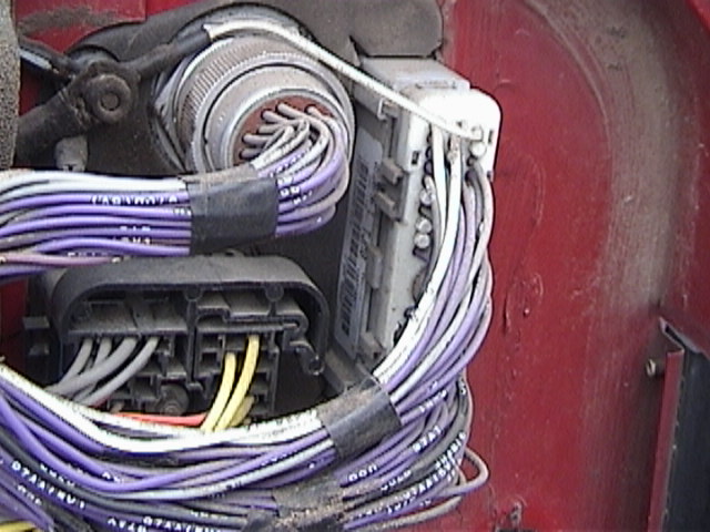
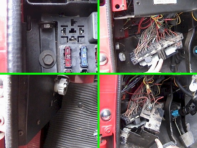
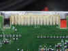
At this point you should see
three connectors protruding through the firewall bulkhead, a square one,
a round one and a rectangle one. The rectangle connector (seen here on
the right) is the PCM connector. Locate the 10mm bolt which is directly
in the center of the connector and unscrew to remove the connector from
the PCM. Do not attempt to remove the bolt from the connector as
it is permanently attached.
|

|
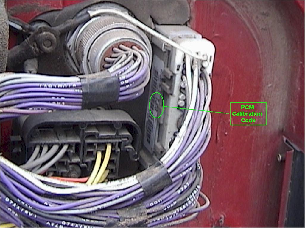
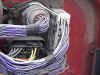
The PCM Code that we will
need in order to program your Phoenix Module will be located here.
|
|
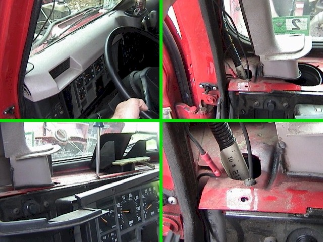
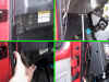
From inside the cab, begin
removing the upper vent panel by removing the two screws that hold it
down. With the vent panel removed, you now have access to remove the
A-pillar panel. Pull the A-pillar cover out from the corner to unsnap the clips.
Remove the 3 upper instrument cluster panel screws, 2 of which are
located at the bottom of the A-pillar, and 1 located to the right of the
instrument cluster.
|
|
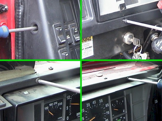
Remove the side dash panel
screw as well as the 4 screws located around the instrument cluster. If
the vehicle is equipped with power windows, there will be a wiring
harness attached to the left side of the dash panel where the window
buttons are located. Disconnect the harness connector and lay the dash
panel aside.
|
|
ONCE AGAIN, PLEASE ENSURE BATTERY IS DISCONNECTED BEFORE PROCEEDING!
Remove both 13 mm bolts (11mm on some applications) that attach the fuse panel
to the bottom of the dashboard. Push the fuse panel down and out of the way as
necessary to allow for clearance. Remove the 4 screws that attach the kick panel
to the body. The kick panel is easily identified by the round diagnostic connector
attached to it.
|
|
Remove the 4 screws attaching
the side panel to the dash panel (1 at the top front, 2 on the bottom
front, and 1 on the bottom underside). With the screws removed, pull
forward on the front dash panel just enough to allow the side bracket to
be twisted out from behind it. Once this is accomplished, pull the side
panel down and away from the dash until it is clear.
|
|
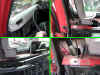
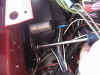
You should now have clear
access to the PCM. Remove the #3 Phillips screw from the PCM mounting
bracket.
|
|
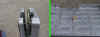
The PCM mounting bracket
(seen here as the black bracket located at an angle and just to the
right of the PCM) must be tilted up from the bottom to disengage the
"hook" at the top of the bracket. This will allow the bracket
and the PCM to be removed. Be careful not to snag any wires when
removing either the bracket or the PCM.
|
|
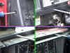
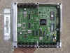
With the PCM removed form the
vehicle, you may now begin the process of cleaning the service
connector. The best method is to remove the 5.5mm (7/32")
bolts that hold the PCM together. There are 6 of them
located on the front cover. This is how the PCM looks with the cover
removed. Please note that you can easily see the 4-digit PCM Code that
is located directly in the middle of the bar code sticker of the PCM.
In this example, the PCM Code is TJM2.
|
|
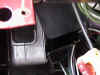
Now separate the back shell
from the main part of the PCM. Be careful not to lose the little plastic
board support.
|
|
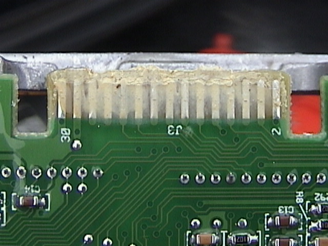
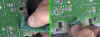
Many computers will have a
coating of lithium (white) grease covering the connector. Remove the
grease using a cloth or paper towel. There will also be a coating of
clear silicone covering the connector.
|
|
Use the provided Scotch-Brite®
pad to clear away the silicone. Acetone (nail polish remover) helps to
clean the connector. DO NOT USE aggressive solvents such as Laquer Thinner
as this will damage the fiberglass resin of the circuit board.
BOTH sides of the connector must be cleaned thoroughly. Failure to
properly clean the connector may cause the vehicle not to start and also
cause damage to the module and/or PCM. Any module or PCM that has been
damaged due to improper installation WILL NOT be covered under warranty.
|
Once the connector is
thoroughly cleaned, temporarily attach the module to the PCM, attach the
PCM to the harness and reconnect the battery. Attempt to start the
vehicle. If vehicle does not start, turn ignition off, disconnect the
battery, remove the PCM, and check the module and connector to ensure
the there are no traces of silicone that would cause erratic operation.
Before calling for technical support, be absolutely certain that ALL
silicone is cleaned from both sides. 98% of No-Start conditions are the
result of poorly cleaned connectors.
|
If all tests pass
satisfactorily, shut off the vehicle and remove the PCM from the
harness. Fasten the module to the
computer using duct or packing tape to help prevent the chip from coming
loose due to vibration. Reassembly if the reverse of the disassembly.
Due to the nature of the module, the PCM bracket will not return to its
original location without modification. You may choose to trim the back end
of the PCM bracket which will uncover the service port on the back of the ECM.
If you cannot trim the bracket, then you may leave the bracket off. However, a
suitable fastening method (such as Velcro) is recommended to prevent the PCM
from rattling against the kick panel while driving.
|