|
MINOTAUR AUTOMOTIVE TUNING SYSTEM
|
|
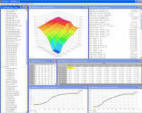
Minotaur Online User's Guide - Working with Definitions
|
|
|
|
Load a memory file if on is not already loaded.
If you want to add to a existing resource definition, load it now.
To create a new resource, right click on the resource type in the overview
window. Select new from the menu.
Right click on the new resource. Select edit from the menu or press
Ctrl-Enter.
|
|
|
|
Working with PARAMETERS
|
|
|
|
The address of a parameter must always be specified. Other items are
optional.
- Name -
This is the name that will be seen by the user. This may be freely changed.
- Address -
This is the address of the parameter in the memory file. This may be different than the address shown in a
disassembly if the PCM memory does not start at address 0x0000. The Ford EEC processor, for example, will
usually start at 0x2000, so the address will be 0x2000 lower in the Minotaur Definition than it is in the
disassembly.
- Units -
The unit of measure - RPM, MPH, Degrees F/C, PSI, etc...
- Adjust -
This the amount that each marked data point will be incremented/decremented using the +/- keys or the mouse
adjustment (per 8 pixels of movement).
- Alt Adjust -
This is the amount that each marked data point will be incremented/decremented using the (Ctrl) key in
conjunction with +/- keys or the mouse adjustment (per 8 pixels of movement).
- Data Type -
The number of bytes and order of the bytes.
- BYTE = 8 bits
- WORD = 16 bits
- DWORD = 32 bits
- FLOAT = 32 bits
- SIGNED = Positive and Negative values
- UNSIGNED = Positive values only
- INTEL = LSB Byte Ordering (Little Endian)
- MOTOROLA = MSB Byte Ordering (Big Endian)
- Start Bit & End Bit -
Reserved for future use.
- Enumeration -
Reserved for future use.
- Format -
This is the number of digits before and after the decimal. This may be in the form %B.Af, where A is the
number of digits after the decimal and B is the number of digits before the decimal. For a hex display,
use %0AX where A is the number of hex digits. An additional character may precede or follow to indicate
that a hex value is displayed. For example $%04X will show $1234 while %04Xh will show 1234h.
- Formula -
This specifies the use of the Scale and Offset values.
- Scale -
This is the multiplier used for unit scaling. Usage is determined by the Formula parameter.
- Offset -
This is the adder used for scaling to meaningful units. Usage is determined by the Formula parameter.
- ID -
This is the name used internally by Minotaur and is not normally displayed to the End User. Once this is
specified, it should not be changed. To maintain consistency, the ID should remain the same for identical
functions of among different Definitions. This is typically less than, but not limited to, 10 characters.
- Level -
This is the lowest User Level that will display this resource.
|
|
|
|
|
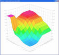
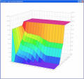
Working with MAPS
|
|
|
|
The address, column count, column step, row count, and row step of a map must
always be specified. The column step is usually 1 and the row step is usually
equal to the column count.
- Name -
This is the name that will be seen by the user. This may be freely changed.
- Address -
This is the address of the parameter in the memory file. This may be different than the address shown in a
disassembly if the PCM memory does not start at address 0x0000. The Ford EEC processor, for example, will
usually start at 0x2000, so the address will be 0x2000 lower in the Minotaur Definition than it is in the
disassembly.
- Units -
The unit of measure - RPM, MPH, Degrees F/C, PSI, etc...
- Adjust -
This the amount that each marked data point will be incremented/decremented using the +/- keys or the mouse
adjustment (per 8 pixels of movement).
- Alt Adjust -
This is the amount that each marked data point will be incremented/decremented using the (Ctrl) key in
conjunction with +/- keys or the mouse adjustment (per 8 pixels of movement).
- Data Type -
The number of bytes and order of the bytes.
- BYTE = 8 bits
- WORD = 16 bits
- DWORD = 32 bits
- FLOAT = 32 bits
- SIGNED = Positive and Negative values
- UNSIGNED = Positive values only
- INTEL = LSB Byte Ordering (Little Endian)
- MOTOROLA = MSB Byte Ordering (Big Endian)
- Format -
This is the number of digits before and after the decimal. This may be in the form %B.Af, where A is the
number of digits after the decimal and B is the number of digits before the decimal. For a hex display,
use %0AX where A is the number of hex digits. An additional character may precede or follow to indicate
that a hex value is displayed. For example $%04X will show $1234 while %04Xh will show 1234h.
- Formula -
This specifies the use of the Scale and Offset values.
- Scale -
This is the multiplier used for unit scaling. Usage is determined by the Formula parameter.
- Offset -
This is the adder used for scaling to meaningful units. Usage is determined by the Formula parameter.
- Min -
This is the lower limit of the graphic display.
- Max -
This is the upper limit of the graphic display.
- Count -
This is the number of rows or columns in the Map.
- Step -
This is the number of bytes between the start of one row/column and the next. For a contiguous full map the
column step will equal row count * data size, or the row step will equal column count * data size (in bytes).
- Labels -
These are the labels for the rows/columns. Separated by '|'. This will be automatically generated if there
is a valid label link to a supporting axis transfer Function.
- Label Link -
This is used to relate a transfer Function to a desired X/Y axis in order to automatically generate Map labels.
You must enter the Function ID name exactly as it is stored in the Function Definition. Case DOES matter.
These are primarily used only for Ford EEC-IV/V processors.
- Label Spacing -
When checked, this sets up the Map so that the row/column spacing is scaled proportionally to the values of the
axis labels. If no labels exist, then a fixed scale using the number of points on that axis will be used. These
are primarily used only for Ford EEC-IV/V processors.
- ID -
This is the name used internally by Minotaur and is not normally displayed to the End User. Once this is
specified, it should not be changed. To maintain consistency, the ID should remain the same for identical
functions of among different Definitions. This is typically less than, but not limited to, 10 characters.
- Default Y Rotation -
This is the Z Axis rotation used for initial display of the map. 45ﭦ will set the map to display in the
lower left corner of the map. This does not affect the ability of the number pad to rotate the map on
any of the 3 axes.
- Browse -
This enables all items in the browse menu. This should be off in a released Resource Definition file.
- Level -
This is the lowest User Level that will display this resource.
|
|
|
|
|
Working with FUNCTIONS
|
|
|
|
The size, X address, X step, Y address, and Y step of a function must
always be specified. Other items are optional.
- Name -
This is the name that will be seen by the user. This may be freely changed.
- Size -
This is the number of entries in the function. This is not the byte count.
- Label -
The label for the axis.
- Address -
This is the address of the parameter in the memory file. This may be different than the address shown in a
disassembly if the PCM memory does not start at address 0x0000. The Ford EEC processor, for example, will
usually start at 0x2000, so the address will be 0x2000 lower in the Minotaur Definition than it is in the
disassembly.
- Step -
The number of bytes between the axis values. If this is negative, the function will be read from highest address
to lowest address.
- Data Type -
The number of bytes and order of the bytes.
- BYTE = 8 bits
- WORD = 16 bits
- DWORD = 32 bits
- FLOAT = 32 bits
- SIGNED = Positive and Negative values
- UNSIGNED = Positive values only
- INTEL = LSB Byte Ordering (Little Endian)
- MOTOROLA = MSB Byte Ordering (Big Endian)
- Units -
The unit of measure - RPM, MPH, Degrees F/C, PSI, etc...
- Format -
This is the number of digits before and after the decimal. This may be in the form %B.Af, where A is the
number of digits after the decimal and B is the number of digits before the decimal. For a hex display,
use %0AX where A is the number of hex digits. An additional character may precede or follow to indicate
that a hex value is displayed. For example $%04X will show $1234 while %04Xh will show 1234h.
- Adjust -
This the amount that each marked data point will be incremented/decremented using the +/- keys or the mouse
adjustment (per 8 pixels of movement).
- Alt Adjust -
This is the amount that each marked data point will be incremented/decremented using the (Ctrl) key in
conjunction with +/- keys or the mouse adjustment (per 8 pixels of movement).
- Min -
This is the lower limit of the graphic display.
- Max -
This is the upper limit of the graphic display.
- Formula -
This specifies the use of the Scale and Offset values.
- Scale -
This is the multiplier used for unit scaling. Usage is determined by the Formula parameter.
- Offset -
This is the adder used for scaling to meaningful units. Usage is determined by the Formula parameter.
- ID -
This is the name used internally by Minotaur and is not normally displayed to the End User. Once this is
specified, it should not be changed. To maintain consistency, the ID should remain the same for identical
functions of among different Definitions. This is typically less than, but not limited to, 10 characters.
- Level -
This is the lowest User Level that will display this resource.
|
|
|
|
|
Remember to save your Defintion before you close the application!
|
|
|
|